> For the complete documentation index, see [llms.txt](https://docs.xviz.com/llms.txt). Markdown versions of documentation pages are available by appending `.md` to page URLs; this page is available as [Markdown](https://docs.xviz.com/performance-management/links.md).
# Links
Other than the parent-child connectors, we can add additional Links i.e., additional connectors for the nodes.
To plot the Links, we need the following information:
1\. Destination node – Id of the destination node
And optional styling details:
2\. Arrow direction – Acceptable values are ‘Start’, ‘End’ and ‘Both’
3\. Style of the line – Acceptable values are ‘Solid’, ‘Dashed’ or ‘Dotted’
4\. Color of the line – Hex color codes are accepted
Example:
Links can be plotted using any of these methods:
### **1. Data-driven Links**
Provide the data for the links from the data source.
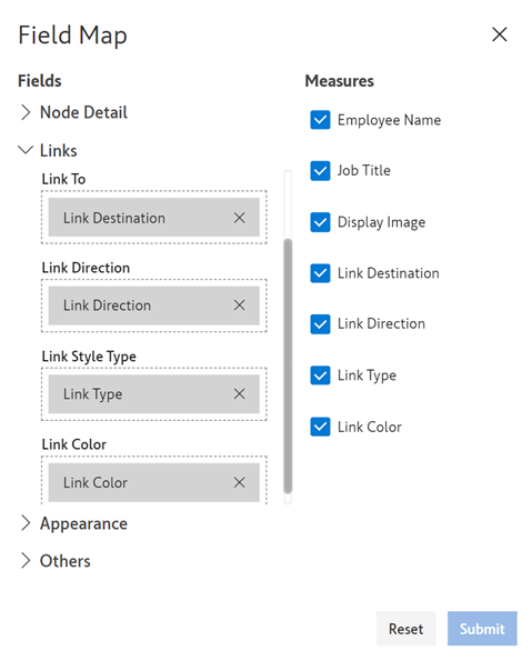
Add the columns in the ‘Fields’ data field and use ‘Map Fields’ to map the columns:
The links are now plotted in the visual:
### **2. Custom Links**
We can draw the connectors within the visual canvas using one of the two mechanisms:
1\. By selecting the source and destination nodes on the canvas:
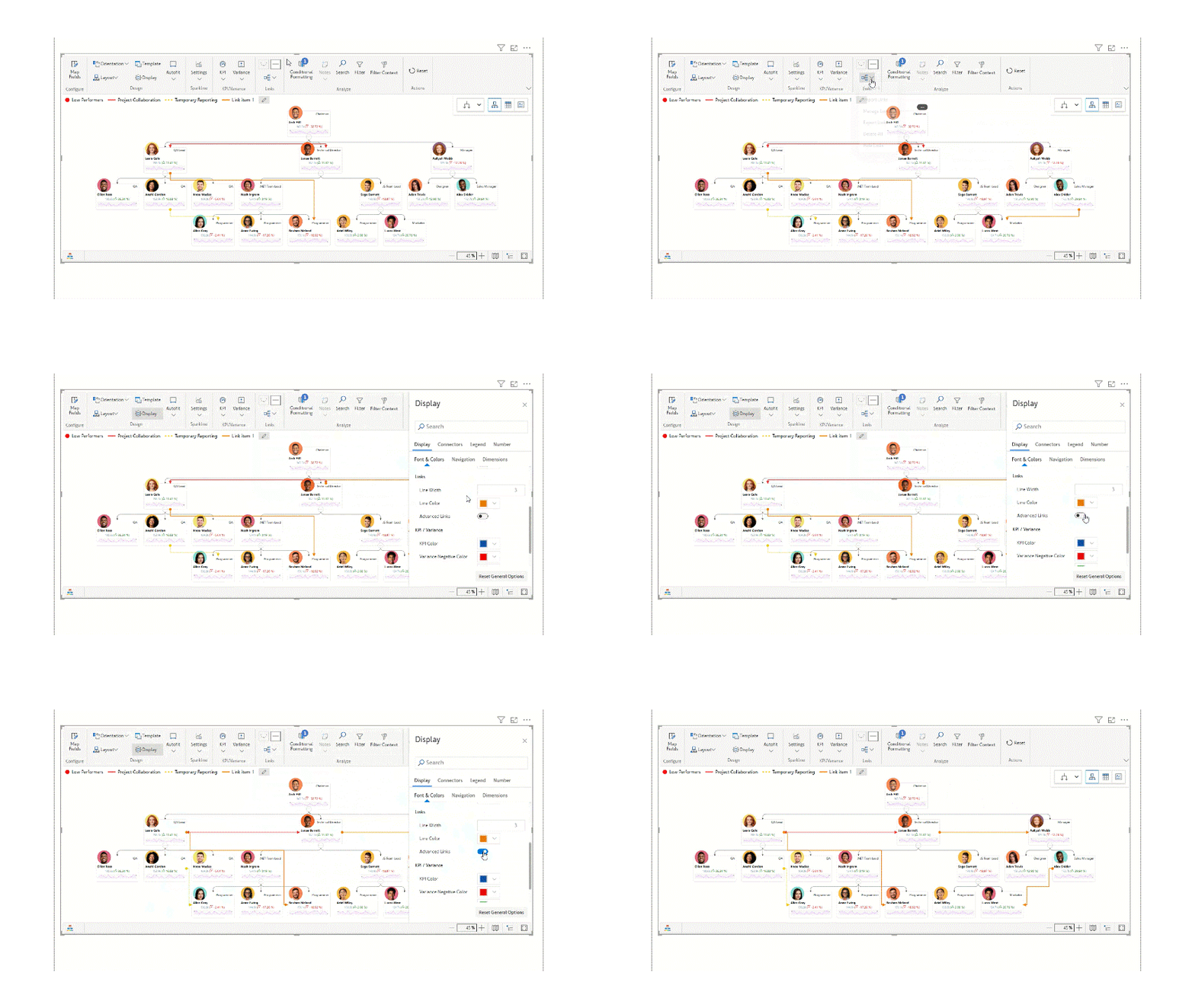
On the top ribbon -> Links section menu -> Select ‘Add Link’
The visual will prompt you to click on the source and then destination nodes. Upon selection, the custom link will be plotted.
2\. By selecting the source and destination nodes using Node Selector:\
On the top ribbon -> Links section menu -> Select ‘Manage Links’
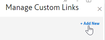
In the ‘Manage Custom Links’ menu, click on ‘Add New’:
Click on ‘Select Node’ for Source and then Destination. A Node Selector will open where we can search for the required node and select it:
We can adjust the formatting for individual links using the ‘Manage Links’ or by clicking on any Link and using the floating menu:
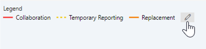
For every kind of link (based on the line style and color), a representation will be added to the Legend. The label for each representation can be set using the ‘Edit’ icon next to the Legend:
### 3. Advanced Links
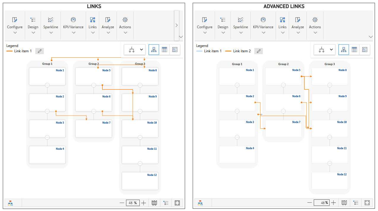
The **Advanced Link** feature provides greater flexibility in visualizing relationships between nodes by improving link positioning and avoiding clutter.
{% hint style="warning" %}
Applicable only for straight links and not curved links
{% endhint %}
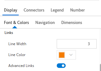
1. Option is available in **Font & Color** section in the **Links** settings
2. When the **Advanced Link** option is enabled, the direction of links automatically adjusts from **side-to-side**.
3. Link Overlapping:
* In scenarios where **Group Nodes** are connected to multiple other nodes, links may overlap, enabling the **Advanced Link** feature reroutes the links, ensuring they are visually distinct and do not overlap unnecessarily.